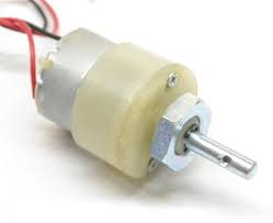
Dc motor:
L293D:
Raspberry Pi:
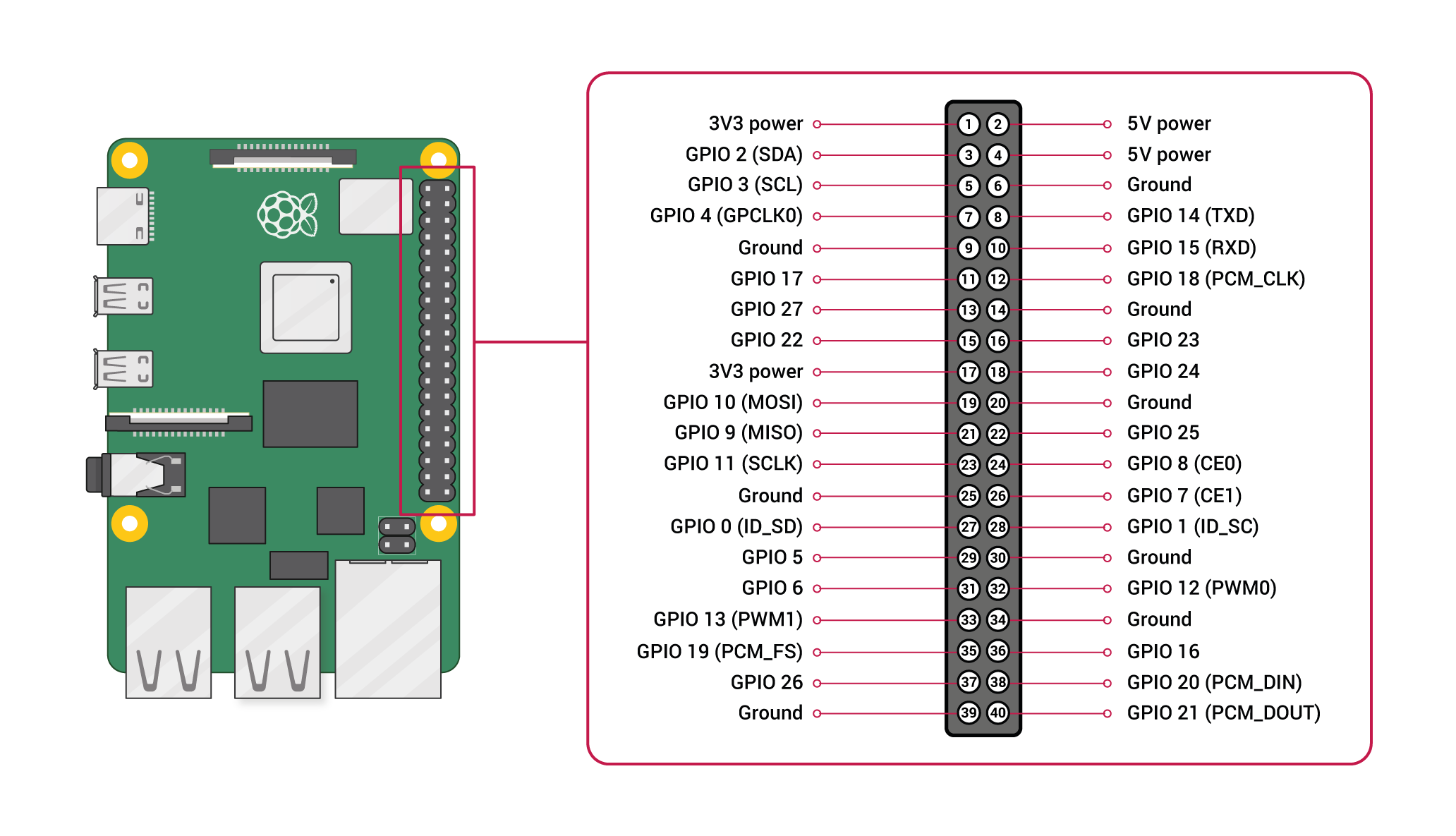
Pin configuration:
1. Vin: Two 5v pins and two 3v3 pins used for providing power supply, where processor works on 3.3v.
DC Motor Pin Configuration with Raspberry pi:

import RPi.GPIO as GPIO
import time
GPIO.setmode(GPIO.BOARD)
IN1=16
IN2=18
GPIO.setup(IN1, GPIO.OUT)
GPIO.setup(IN2, GPIO.OUT)
print (“FORWARD MOTION”)
GPIO.OUTPUT(IN1, GPIO.HIGH)
GPIO.OUTPUT(IN2, GPIO.LOW)
time.sleep(3)
print (“BACKWARD MOTION”)
GPIO.OUTPUT(IN1, GPIO.LOW)
GPIO.OUTPUT(IN2, GPIO.HIGH)
time.sleep(3)
print (“Motor Stop”)
GPIO.OUTPUT(IN1, GPIO.LOW)
GPIO.OUTPUT(IN2, GPIO.LOW)
GPIO.cleanup()